martin-ger/esp32_nat_router

A simple NAT Router for the ESP32
| repo name | martin-ger/esp32_nat_router |
| repo link | https://github.com/martin-ger/esp32_nat_router |
| homepage | |
| language | C |
| size (curr.) | 4490 kB |
| stars (curr.) | 259 |
| created | 2020-02-17 |
| license | |
ESP32 NAT Router
This is a firmware to use the ESP32 as WiFi NAT router. It can be used as
- Simple range extender for an existing WiFi network
- Setting up an additional WiFi network with different SSID/password for guests or IOT devices
It can achieve a bandwidth of more than 15mbps.
The code is based on the Console Component and the esp-idf-nat-example.
Performance
All tests used IPv4 and the TCP protocol.
| Board | Tools | Optimization | CPU Frequency | Throughput | Power |
|---|---|---|---|---|---|
ESP32D0WDQ6 |
iperf3 |
0g |
240MHz |
16.0 MBits/s |
1.6 W |
ESP32D0WDQ6 |
iperf3 |
0s |
240MHz |
10.0 MBits/s |
1.8 W |
ESP32D0WDQ6 |
iperf3 |
0g |
160MHz |
15.2 MBits/s |
1.4 W |
ESP32D0WDQ6 |
iperf3 |
0s |
160MHz |
14.1 MBits/s |
1.5 W |
First Boot
After first boot the ESP32 NAT Router will offer a WiFi network with an open AP and the ssid “ESP32_NAT_Router”. Configuration can either be done via a simple web interface or via the serial console.
Web Config Interface
The web interface allows for the configuration of all parameters. Connect you PC or smartphone to the WiFi SSID “ESP32_NAT_Router” and point your browser to “http://192.168.4.1”. This page should appear:
First enter the appropriate values for the uplink WiFi network, the “STA Settings”. Leave password blank for open networks. Click “Connect”. The ESP32 reboots and will connect to your WiFi router.
Now you can reconnect and reload the page and change the “Soft AP Settings”. Click “Set” and again the ESP32 reboots. Now it is ready for forwarding traffic over the newly configured Soft AP. Be aware that these changes also affect the config interface, i.e. to do further configuration, connect to the ESP32 through one of the newly configured WiFi networks.
If you want to enter a ‘+’ in the web interface you have to use HTTP-style hex encoding like “Mine%2bYours”. This will result in a string “Mine+Yours”. With this hex encoding you can enter any byte value you like, except for 0 (for C-internal reasons).
It you want to disable the web interface (e.g. for security reasons), go to the CLI and enter:
nvs_namespace esp32_nat
nvs_set lock str -v 1
After restart, no webserver is started any more. You can only re-enable it with:
nvs_namespace esp32_nat
nvs_set lock str -v 0
If you made a mistake and have lost all contact with the ESP you can still use the serial console to reconfigure it. All parameter settings are stored in NVS (non volatile storage), which is not erased by simple re-flashing the binaries. If you want to wipe it out, use “esptool.py -p /dev/ttyUSB0 erase_flash”.
Interpreting the on board LED
If the ESP32 is connected to the upstream AP then the on board LED should be on, otherwise off. If there are devices connected to the ESP32 then the on board LED will keep blinking as many times as the number of devices connected.
For example:
One device connected to the ESP32, and the ESP32 is connected to upstream:
*****.*****
Two devices are connected to the ESP32, but the ESP32 is not connected to upstream:
....*.*....
Command Line Interface
For configuration you have to use a serial console (Putty or GtkTerm with 115200 bps). Use the “set_sta” and the “set_ap” command to configure the WiFi settings. Changes are stored persistently in NVS and are applied after next restart. Use “show” to display the current config. The NVS namespace for the parameters is “esp32_nat”
Enter the help command get a full list of all available commands:
help
  Print the list of registered commands

free
  Get the current size of free heap memory

heap
  Get minimum size of free heap memory that was available during program execu
  tion

version
  Get version of chip and SDK

restart
  Software reset of the chip

deep_sleep  [-t <t>] [--io=<n>] [--io_level=<0|1>]
  Enter deep sleep mode. Two wakeup modes are supported: timer and GPIO. If no
  wakeup option is specified, will sleep indefinitely.
  -t, --time=<t>  Wake up time, ms
      --io=<n>  If specified, wakeup using GPIO with given number
  --io_level=<0|1>  GPIO level to trigger wakeup

light_sleep  [-t <t>] [--io=<n>]... [--io_level=<0|1>]...
  Enter light sleep mode. Two wakeup modes are supported: timer and GPIO. Mult
  iple GPIO pins can be specified using pairs of 'io' and 'io_level' arguments
  . Will also wake up on UART input.
  -t, --time=<t>  Wake up time, ms
      --io=<n>  If specified, wakeup using GPIO with given number
  --io_level=<0|1>  GPIO level to trigger wakeup

tasks
  Get information about running tasks

nvs_set  <key> <type> -v <value>
  Set key-value pair in selected namespace.
Examples:
 nvs_set VarName i32 -v
  123
 nvs_set VarName str -v YourString
 nvs_set VarName blob -v 0123456789abcdef
         <key>  key of the value to be set
        <type>  type can be: i8, u8, i16, u16 i32, u32 i64, u64, str, blob
  -v, --value=<value>  value to be stored

nvs_get  <key> <type>
  Get key-value pair from selected namespace.
Example: nvs_get VarName i32
         <key>  key of the value to be read
        <type>  type can be: i8, u8, i16, u16 i32, u32 i64, u64, str, blob

nvs_erase  <key>
  Erase key-value pair from current namespace
         <key>  key of the value to be erased

nvs_namespace  <namespace>
  Set current namespace
   <namespace>  namespace of the partition to be selected

nvs_list  <partition> [-n <namespace>] [-t <type>]
  List stored key-value pairs stored in NVS.Namespace and type can be specified
  to print only those key-value pairs.

Following command list variables stored inside 'nvs' partition, under namespace 'storage' with type uint32_t
  Example: nvs_list nvs -n storage -t u32

   <partition>  partition name
  -n, --namespace=<namespace>  namespace name
  -t, --type=<type>  type can be: i8, u8, i16, u16 i32, u32 i64, u64, str, blob

nvs_erase_namespace  <namespace>
  Erases specified namespace
   <namespace>  namespace to be erased

set_sta  <ssid> <passwd>
  Set SSID and password of the STA interface
        <ssid>  SSID
      <passwd>  Password

set_sta_static  <ip> <subnet> <gw>
  Set Static IP for the STA interface
          <ip>  IP
      <subnet>  Subnet Mask
          <gw>  Gateway Address

set_ap  <ssid> <passwd>
  Set SSID and password of the SoftAP
        <ssid>  SSID of AP
      <passwd>  Password of AP

set_ap_ip  <ip>
  Set IP for the AP interface
          <ip>  IP

portmap  [add|del] [TCP|UDP] <ext_portno> <int_ip> <int_portno>
  Add or delete a portmapping to the router
     [add|del]  add or delete portmapping
     [TCP|UDP]  TCP or UDP port
  <ext_portno>  external port number
      <int_ip>  internal IP
  <int_portno>  internal port number

show
  Get status and config of the router
If you want to enter non-ASCII or special characters (incl. ' ‘) you can use HTTP-style hex encoding (e.g. “My%20AccessPoint” results in a string “My AccessPoint”).
Flashing the prebuild Binaries
Install esptool, go to the project directory, and enter:
esptool.py --chip esp32 --port /dev/ttyUSB0 \
--baud 115200 --before default_reset --after hard_reset write_flash \
-z --flash_mode dio --flash_freq 40m --flash_size detect \
0x1000 build/bootloader/bootloader.bin \
0x10000 build/esp32_nat_router.bin \
0x8000 build/partitions_example.bin
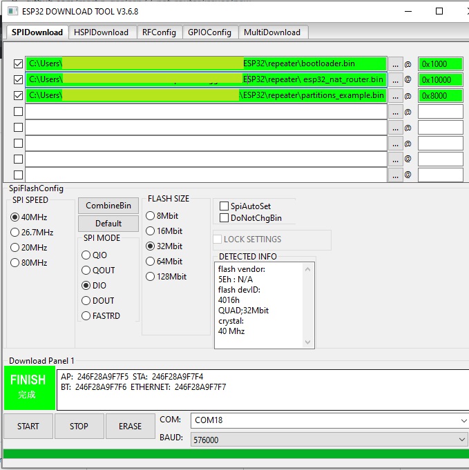
As an alternative you might use Espressif’s Flash Download Tools with the parameters given in the figure below (thanks to mahesh2000):
Building the Binaries
The following are the steps required to compile this project:
-
Download and setup the ESP-IDF.
-
In the project directory run
make menuconfig(oridf.py menuconfigfor cmake).- *Component config -> LWIP > Enable copy between Layer2 and Layer3 packets.
- *Component config -> LWIP > Enable IP forwarding.
- *Component config -> LWIP > Enable NAT (new/experimental).
-
Build the project and flash it to the ESP32.
A detailed instruction on how to build, configure and flash a ESP-IDF project can also be found the official ESP-IDF guide.
DNS
As soon as the ESP32 STA has learned a DNS IP from its upstream DNS server on first connect, it passes that to newly connected clients. Before that by default the DNS-Server which is offerd to clients connecting to the ESP32 AP is set to 8.8.8.8. Replace the value of the MY_DNS_IP_ADDR with your desired DNS-Server IP address (in hex) if you want to use a different one.
Troubleshooting
Line Endings
The line endings in the Console Example are configured to match particular serial monitors. Therefore, if the following log output appears, consider using a different serial monitor (e.g. Putty for Windows or GtkTerm on Linux) or modify the example’s UART configuration.
This is an example of ESP-IDF console component.
Type 'help' to get the list of commands.
Use UP/DOWN arrows to navigate through command history.
Press TAB when typing command name to auto-complete.
Your terminal application does not support escape sequences.
Line editing and history features are disabled.
On Windows, try using Putty instead.
esp32>